Engineering case study Laser metal deposition
Inside the LMD
control system.
I built this system to connect the physical LMD process with its cameras, sensors, machine interfaces and control decisions. I led the architecture, development and integration, coordinating contributors working on sensors and algorithms.
Monitoring and control deployed across three machines at two sites. The work includes camera-based height sensing, practical optical calibration and manufacturing records. AI and modelling support measurement, experiment planning and process control within this engineering workflow.
About the images. The supervisory and calibration panels are offline demonstrations of the actual GUI, with example readings and states. The process-viewer capture below shows the path display and camera views separately. Click any screenshot to inspect it at full resolution.
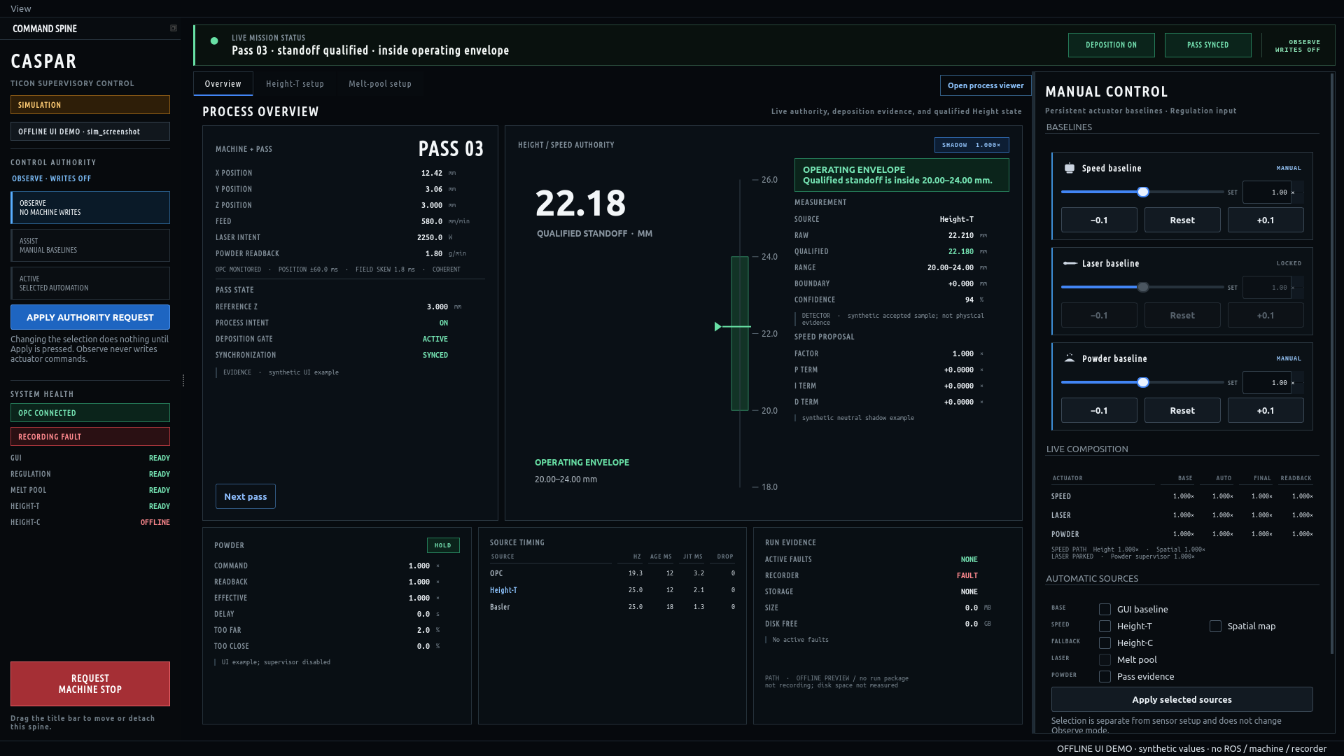
The interface keeps machine context, measurement status and control authority visible together. The recording-fault indicator belongs to the non-running demo recorder; it is not a production fault report.
I built this system to connect the parts of laser metal deposition that an operator has to understand together: the machine, the deposited material, the sensor measurements and the next process decision.
Laser metal deposition (LMD) is a directed energy deposition process. A laser creates a melt pool while material is added along a programmed path. As the build grows, the distance to the surface, local geometry and process response change. The control software needs to interpret those changes in the context of the actual machine movement.
My work brings modelling, monitoring, simulation, toolpath development and control into one engineering workflow. A conversational layer helps the user prepare an experiment, approve its execution and review the results. Underneath it, modular sensor and machine interfaces make the architecture adaptable to different equipment.
Give the operator a coherent view of the process.
The panel has three working areas. The left column shows operating authority and system health. The centre explains the current process state. The right rail keeps manual baselines and the selected automatic sources in view.
This arrangement answers practical questions: Is deposition happening? Which height measurement is being used? Is the data current? Is the software only observing, or is an adjustment allowed to reach the machine?
Know what is enabled.
Observe, Assist and Active describe different levels of control. Health indicators expose missing sources and recording problems. A requested change must be applied explicitly.
Read measurements in context.
Machine position, pass identity, stand-off, operating limits and source timing sit alongside each other. Raw values and accepted measurements have distinct roles.
See how a command is formed.
Manual baselines, automatic contributions, final factors and machine readback are shown separately. Source selection is visible rather than hidden inside an algorithm.
The stop request in the GUI is a supervisory action. Machine interlocks, motion authority and the safety-rated stopping function remain with the machine controller.
Put the toolpath and camera views beside each other.
The process viewer connects the programmed deposition path to the current machine position and the optical measurements. On the left, the G-code path and position marker sit over a spatial map of raw stand-off observations. On the right, the coaxial melt-pool view shows the deposition region, while the triangulation camera exposes the feature used to estimate nozzle-to-surface distance for height control.
Seeing these together helps an engineer relate a change in the camera image to a particular part of the path. The viewer is read-only: closing it does not interrupt acquisition or control.
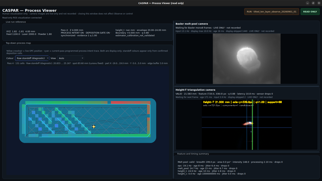
Left: programmed path, position and raw diagnostic map. Top right: coaxial melt pool. Bottom right: triangulation feature and measurement overlay. This capture reports an unvalidated calibration; the displayed raw values are not qualified control measurements. Camera images in this viewer are live-only and are not recorded by the viewer.
Three AI agents, from experiment idea to analysis.
I built a three-agent workflow around experiments. The user can explain what they want to investigate, which physical systems are connected and why the experiment matters. The agents connect that conversation to preparation, approved execution and analysis.
- 01 / Describe
Manager agent
The user's conversational point of contact. The user describes the experiment, the connected equipment and the motivation. The Manager carries that context into preparation and receives the analysis report after the run.
- 02 / Confirm & run
Operator agent
Asks questions and requests explicit confirmations before taking over. With the user's approval, it coordinates the required checks, machine and software startup, and data recording for the agreed experiment.
- 03 / Review
Analysis agent
After the experiment is stopped, it analyses the recorded data and prepares a report for the Manager. The user can then discuss the results through the same conversation that began the experiment.
Experiment intent → questions and approval → execution → analysis → back to the Manager.
Make the procedure accessible to someone new to the setup.
The aim is to reduce how much specialist software knowledge a user needs before conducting an experiment. Someone learning the equipment can describe a goal and be guided through the missing details, instead of already knowing every sensor interface, launch command and analysis script.
The agents coordinate the experiment; the supervisory controller still governs which machine actions are available. User approval does not bypass calibration, commissioning limits or machine interlocks. Physical preparation and operation still require the appropriate equipment training.
Different sensors. A shared process context.
I chose Robot Operating System 2 (ROS 2) as the integration layer so that people could develop sensors, algorithms and machine interfaces independently. Each component publishes a defined message. The rest of the system can consume that message without taking over the component's internal implementation.
The central engineering problem is alignment. Cameras and machine interfaces update at different times. The backend uses timestamped machine history to associate an optical measurement with the relevant position and pass. It also tracks uncertainty, so a delayed or ambiguous sample does not silently become a precise point on a process map.
| Input | What it contributes | How it is used |
|---|---|---|
| Machine state | Position, feed, laser and powder state, overrides and connection health. | OPC UA provides the machine context needed to interpret camera measurements. |
| Height-T | A triangulation-camera measurement of nozzle-to-surface stand-off. | Calibration, feature checks and timing determine whether a measurement can inform control. |
| Height-C | An alternative height-measurement input. | Designed as a selected fallback source; it is not averaged with Height-T. |
| Melt-pool camera | Process presence, image features and a live view of the deposition region. | Feedback for managing heat input and maintaining a stable melt pool through laser-power, travel-speed and powder-feed adjustments. |
| Toolpath & pass | A read-only copy of the planned path and the current deposition pass. | Measurements are associated with position, path segments and layers for spatial review. |
| Operator & job | Mode, manual baselines, enabled sources, calibration and operating limits. | The selected job provides the context and limits for interpreting data and proposing changes. |
A connected sensor still needs calibration, units, timing information and a valid operating range. This is what makes modular integration useful in practice: every module has an explicit responsibility, including how it reports missing or unreliable data.
Make the measurement explainable before using it for control.
I developed camera-based height sensing from concept to tested prototype, working with the optical setup, illumination, image processing and calibration. This is a practical extension of my lasers and photonics background in a laser-material processing environment.
Height-T estimates stand-off from a camera view. The setup workflow connects image coordinates to physical references and makes the assumptions visible to the person commissioning the sensor. The tested-prototype result does not establish a certified accuracy or a universal operating range.
The operator establishes the physical reference, waits for the measurement to settle, then captures a short numeric window. Approved reference windows can be reviewed and saved in a calibration receipt. The software does not choose or verify the physical reference on the operator's behalf.
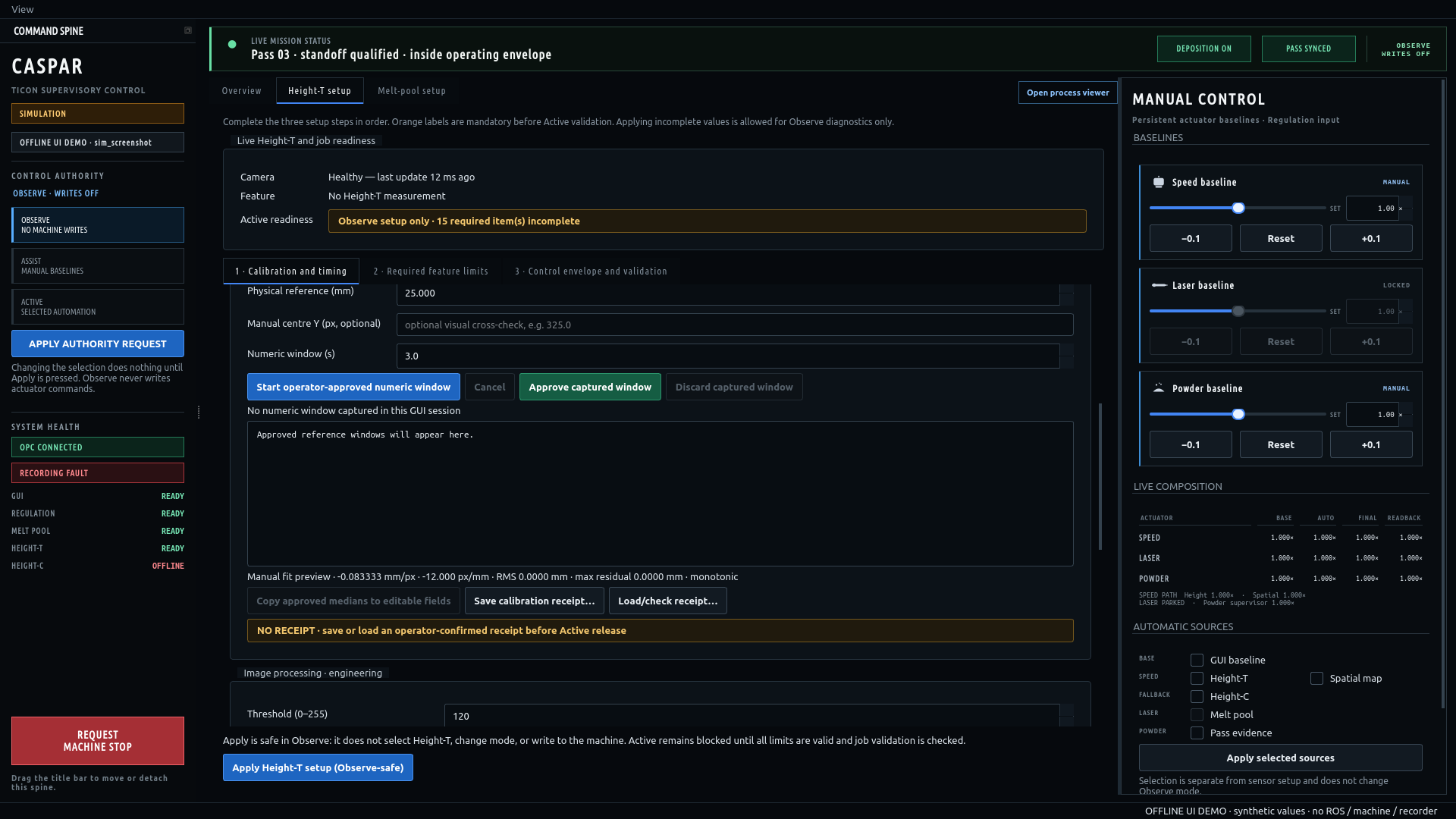
A guided sequence makes the physical reference, captured values and operator approval explicit. The example has no approved receipt and is not ready for Active operation.
Keep image-processing choices visible.
The engineering panel exposes thresholding, morphology, image geometry, the nozzle-axis corridor and the measurement strip. These settings define where the detector looks and what kind of feature it accepts.
This matters when illumination, reflections or deposition geometry change. A numerical output can look plausible even when the detector is following the wrong feature. The setup makes it possible to inspect the measurement logic alongside the camera image.
Preserve the reasons a sample was rejected.
Feature limits and diagnostics help distinguish an accepted measurement from an optical disturbance. The interface exposes checks for image clipping, bright regions, competing peaks and feature shape, with an optional diagnostic overlay.
The software also considers freshness and abrupt changes. Raw observations remain useful for investigation even when they are unsuitable for automatic correction. Keeping both the value and its validity state is essential for understanding a run afterwards.
A control architecture with explicit authority.
The architecture separates measurement, interpretation, proposed action and the final machine-facing command. That separation makes it possible to follow a control decision from the sensor data to the adjustment sent to the machine.
- 01
Acquire
Machine, cameras and operator inputs
- 02
Align
Time, position and deposition pass
- 03
Qualify
Freshness, calibration and validity
- 04
Propose
Bounded process adjustments
- 05
Apply & record
Permitted commands, readback and history
Three timescales for three different problems.
Immediate stand-off correction. The fast control path calculates a bounded speed adjustment from accepted height data and a configured operating envelope. Hysteresis and rate limits constrain its response. Stale or rejected measurements remove automatic authority rather than leaving an old correction in charge.
Memory of the previous pass. The spatial path associates measurements with regions of the build. Its purpose is to prepare a correction when the nozzle revisits a region on a later pass. Uncertain pass identity or alignment prevents that map from silently influencing control.
Slower powder adaptation. Powder transport has a delay. The supervisory design therefore separates the requested setting, machine readback and estimated material arrival. Its decisions use longer evidence windows instead of reacting to every camera sample.
Keep the melt pool stable throughout the build.
Melt-pool feedback helps manage heat input and temperature as deposition progresses. The aim is a pool with a consistent size, shape and behaviour along the toolpath. Camera measurements describe how the pool is changing and guide adjustments to laser power, travel speed or powder feed. These variables influence the balance between energy input and added material, so the controller coordinates their response within the selected process limits.
Observe
Acquire, interpret and record. No machine writes. Use it to inspect signals, timing and proposed responses.
Assist
Permit deliberate operator baseline adjustments through the guarded command path, within the configured process limits.
Active
Selected automatic contributions can influence permitted actuators only after their measurement and machine interface have been qualified.
A single regulation layer combines the allowed contributions. Commands carry identity, expiry and bounds, and the interface checks readback. ROS 2 coordinates this supervisory layer; the CNC or robot controller continues to execute motion and enforce the machine's own interlocks.
Reuse the architecture. Engineer the machine connection.
My monitoring and control work has been deployed across three machines at two sites. It began on a three-axis CNC LMD machine and was then adapted for a KUKA robot and the wide-track BreitbahnDED machine, spanning Exafuse and the ZESS research environment at Ruhr University Bochum.
The transferable part is the structure: sensor messages, measurement interpretation, control proposals, operator views and build records. Machine adapters translate equipment-specific signals into that common structure. Job profiles supply the relevant calibration, timing and operating limits.
A new machine still needs its own engineering work. I need to establish which interfaces are available, what the signals actually mean, how quickly they update and how a permitted command changes the process. Different sensors can then be introduced through the same message contracts, with their own calibration and validity checks.
Shared across the system
Sensor contracts · timestamps · validity states · control structure · operator workflow · run identity
Established for each machine
Interfaces · coordinate conventions · timing · calibration · actuator response · process limits · commissioning
Keep the data that explains the decision.
A live dashboard answers what is happening now. An engineering record must also explain what happened, which configuration was in use and why a particular action was proposed or rejected.
The data architecture separates the live control path from operator views and storage. Local history and ROS recording retain measurements, state and decisions. A run package brings these together with the relevant toolpath, effective settings and logs. A saved hash inventory lets the recorded files be checked for later changes.
In parallel, asynchronous telemetry passes through RabbitMQ into InfluxDB for Grafana dashboards and comparison. Storage and dashboard updates are kept outside the control callback path. Simulation and production records carry distinct identifiers.
At company level, I built the in-house MES/ERP and the operator procedures around it. The system connects quotations, costing, scheduling and manufacturing records. Print-ID traceability links planning, production monitoring and quality documentation.
The workflow is used by every operator. That adoption gives the control-system record a place in the history of the part, with procedures that connect shop-floor activity to usable data and documentation.
Monitoring supports process investigation and quality review. Final part acceptance still depends on the required inspection, testing and engineering judgement.
Build, test and extend the system in stages.
The wider research includes heat-transfer and deposition simulation, physics-informed bead models, parameter studies and experimental comparison. These tools help me investigate process behaviour before machine trials.
The runtime simulator serves a different purpose: exercising interfaces, sensor faults, delays and controller behaviour in a controlled environment. It is not a validated prediction of the physical process. Likewise, the supervisory system reads an existing toolpath for context; toolpath development is a separate part of my engineering work.
This distinction is useful during development. A software interface test, a successful monitoring run and a physical closed-loop trial answer different questions. Each provides evidence for the next stage.
My contribution
I led the system architecture and development, the selection and interpretation of sensor data, and the integration of machine interfaces, software and manufacturing workflows. I also coordinated contributors working on sensors and algorithms. This work forms part of my doctoral research and my R&D role at Exafuse.
For the 2024 Duisburg bridge components, my responsibility covered process monitoring and control that enabled unattended builds, together with delivery scheduling within my scope. Testing was outside my role; the wider company and partner results remain separately attributed. The planning, monitoring and control methods from that work informed later projects.
I also led Exafuse's contribution to BreitbahnDED, including technical coordination, milestones, costs and reporting. The broader engineering goal is an operator workflow that carries process knowledge in the system, while keeping its measurements and decisions open to inspection.